
Design of Stopwatch based on STC89C52 Single Chip Microcomputer
Abstract
This design is according to the requirements of the wide rider, and the Multi-function bike computer has the function of velocity measurement, display, timing, lighting, buzzer warning, which could satisfy the requirements of cycling enthusiasts. This design is based on STC89C52 SCM (Single Chip Microcomputer) smallest system and uses hall sensor receives the bicycle wheel rotation numbers date, and then transmit the received data into the SCM. After the SCM’s calculation and processing, it gets the bicycle’s instantaneous speed, mileage, riding time through the LED display the date. The part of software programming use C language, which compiles and downloads by the Keil and STC-ISP. This design uses Proteus to make the circuit diagram drawing and system simulation. The overall program adopted modular approach, and each module has a special function. The idea which makes the program more clear, is advantageous to the optimization of code logic and modification.
Author Contributions
Copyright © 2022 Wei Wang, et al.
 This is an open-access article distributed under the terms of the Creative Commons Attribution License, which permits unrestricted use, distribution, and reproduction in any medium, provided the original author and source are credited.
Competing interests
The authors have declared that no competing interests exist.
Citation:
Introduction
Introduction of Bicycle Code Table
Bicycle code table is used to calculate and display the bicycle speed and mileage of an electronic product1. It is composed of an induction magnet installed on the spoke of the front wheel of the bicycle, a sensor inserted in front, a connection line between the sensor's code table and a code table on the grip seat, as shown in Figure 1, a common code table on the market2.
Figure 1.Common code watch in the market
Code table working principle: the ring in rotation by the sensor to capture the induction magnet to bring the bicycle driving state information, through the connection line transmission to the code table, the host code table after processing the processor calculated speed, mileage and other information, and display in the code table interface3.
Research Background and Significance
Bicycle code watch foreign famous brands are mainly Germany's Sigma and BOAO, Japan's CATEYE and other representative brands, China's domestic brands are BOGEER, shun east and a large number of manufacturers are producing and selling4.
The quality of foreign brands is relatively reliable, the service life is longer, but the price of foreign code watch will be higher, but the function is relatively less5. Relative to foreign brands, the domestic production of code watch manufacturers appear to be mixed, all kinds of brands and various functions of the code watch have been developed and produced, to meet the needs of the majority of domestic cyclists6.
The function of the clock on the market now many are single, only to measure the speed, mileage, show time, etc., although can realize many basic functions, but there are some function can't meet the demand of the bicycle amateur, waste economy, price is low, not very good grasp activists current activity7, Thus, the purpose of daily travel and exercise and entertainment can not be well realized. However, this design can realize the dual purpose of daily travel and exercise and entertainment, and the cost performance will be higher than that of amateurs8.
Design Task
The Design Requirements.
(1) By referring to the relevant information, to understand the basic working principle of bicycle code table.
(2) It is required to design a bicycle code table that can be used in different types of bicycles. The LCD display can display information such as current speed, mileage and time.
(3) Draw the circuit diagram and design the hardware circuit.
(4) Draw a flow chart and compile the program.
(5) Use simulation software to simulate.
Design Scheme.
(1) Using STC89C52 microcontroller as the processing chip.
(2) Use Hall sensor with induction magnet to receive the number of bicycle wheel turns.
(3) Use LCD1602 to display bicycle speed, mileage and other information and system Settings and other system Settings menu.
(4) Use Proteus to draw circuit diagram, simulation, Keil and STC-ISP to compile and download the program.
(5) Can manually set the wheel diameter of the bicycle, in order to improve the accuracy of the measurement of different types of bicycles, to provide speed, mileage, average speed, time and other information.
(6) It can preset the amount of exercise (such as preset speed and mileage) and realize the alarm function when the actual speed exceeds the preset value.
(7) Use DS1302 chip to realize clock setting and data storage.
Using the above scheme, hall sensor is induced to the bicycle wheel rotation within a certain amount of time the number of times, and then adjust the motion information of the bike through the modulation circuit for digital pulse signal, then the pulse signal transmission to the STC89C52 single-chip computer calculation and processing of the data, using SCM will analyze these pulses data processing, Calculate the instantaneous speed of the bicycle and the form of the mileage, and finally display to the rider.
System Hardware Part Design and Introduction
System Hardware Design
System hardware design mainly includes system analysis, selection of suitable hardware, circuit drawing, lap hardware circuit, hardware system debugging and improvement stages. Before the design, we should fully understand the content of our design, design a good implementation of the system, draw a good circuit diagram, understand the principle and function of each part of the circuit, after the circuit is built into the debugging stage.
The general idea of the system is as follows: assuming that the circumference of the wheel ring is L and a permanent magnets are installed on the wheel ring, the maximum error of the measured mileage value is L/ A. After comprehensive analysis, a=1 is chosen in this design. When the wheel every turn, through the switch type Hall element sensor will collect a pulse signal, and input from pin P3.2 interrupt 0 end, the sensor every get a pulse signal that provides a count interrupt to the system. Each break represents one turn of the wheel, and the product of the number of breaks N and the circumference L of the wheel ring is the mileage value. Counter T1 calculates the time taken for each revolution and calculates the instant speed speed. If the bicycle exceeds the speed limit, the system will send out an alarm signal and the buzzer will sound.
Figure 2 is the system circuit diagram drawn by Proteus drawing simulation software.
Figure 2.System circuit diagram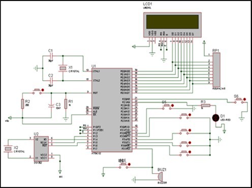
Minimum System of Single Chip Microcomputer
Introduction of STC89C52 Single Chip Microcomputer
Since the development of single chip microcomputer, it has been used more and more widely. because single chip microcomputer has rich functions, small size, easy to carry, low price and stable performance, more and more electronic design enthusiasts begin to learn to use single chip microcomputer.
The 51 single-chip microcomputer is the first to be manufactured and sprung up in the whole single-chip microcomputer series.
The classic 51 series single-chip microcomputer has very rich functions and complete instruction system. Because of its earliest rise and long development time, 51 series single-chip microcomputer is the most mature single-chip microcomputer.
Figure 3 shows the pin diagram of the STC89C52 single-chip microcomputer.
Figure 3.Pin diagram of STC89C52 SCM
Functions of 51 Microcontroller:
8-bit central processing unit (CPU);
4KB/8KB/16KB program memory (ROM);
128B/256B/512B data memory (RAM);
There are 32 PARALLEL I/O interface lines;
There are 111 single-chip microcomputer instructions, and most of them are single-byte instructions;
MCU internal multiple registers with special functions;
There are two programmable timing/counters in the MCU.
A total of 5 interrupt sources, 2 priority;
There is a full-duplex serial communication port;
The addressing space of the external data storage is 64kB;
The addressing space of the external program memory is 64kB;
With logical operation bit addressing function;
Double in-line 40 pin package;
Single +5V power supply;
The central processing unit (CPU) consists of the arithmetic logic unit (ALU) and the control logic processor, including the interrupt system and some external special function registers;
RAM: it stores the data that can be read and written by the single chip microcomputer, such as the data to be displayed and the results of operation, etc.
ROM: microcontroller can only read data from it, can not write data, the data inside are written before the appearance of storage, can not be modified;
I/O ports: FOUR 8-bit parallel I/O ports P0, P1, P2, and P3 for input and output.
T/C: Two timing/registers. Control instructions can make it work in timing mode, can also work in technical mode;
Interrupt control system with five interrupt sources;
A full-duplex UART (universal asynchronous receiver and transmitter) serial I/O port, used to realize the serial communication between microcontrollers or between microcontrollers and microcomputers;
On-chip oscillator and clock generation circuit, crystal oscillator and regulation circuit need to be connected externally. The best oscillation frequency is 6M -- 12M.
Several Commonly Used Registers:
There are 21 registers with special function in 51 single-chip microcomputer, and the address space is distributed between 80H and FFH. Special function register means that there is a separate storage location in the single-chip microcomputer to control some special devices (such as timer, counter, I hand O port, interrupt, etc.).
The GATE of TMOD (timer control register) is used for timing operation of switch control bits. If GATE=1, pin INT0 or INT1 is high. At the same time, when the CONTROL bit TR0 or TR1 in TCON is 1, the timing/counter 0 or 1 starts to work. If GATE=0, simply set the TR0 or TR1 control bit to 1 and the timer/counter 0 or 1 starts working.
C/T is the selector bit for the timer or counter function. C/T=1 is the counter, and the count pulse is input through the external pin T0 or T1. When C/T=0, it is the timer, and the internal system clock provides the timing working pulse.
M1, M0, T0, T1 are working mode bit selections.
Table 1 shows the selection of working mode bits
The working mode of the timer control register is selected as shown in Table 2.
Table 1. Work mode bit mode selection| M1 | M0 | Working mode. |
|---|---|---|
| 0 | 0 | Mode 0pr 13-bit count / timer. |
| 0 | 1 | Mode, 1pm 16-bit count / timer. |
| 1 | 0 | Mode 2pr 8-bit auto-load count / timer. |
| 1 | 1 | Mode 3, only applicable to T0, timer 0 is divided into two independent 8-bit timers / counters TH0 and TL 0,T 1 stop working in mode 3 |
| TCON timer control register | |||||||
|---|---|---|---|---|---|---|---|
| B7 | B6 | B5 | B4 | B3 | B2 | B1 | B0 |
| TF1 | TR1 | TF0 | TR0 | IE1 | IT1 | IE0 | IT0 |
Oscillation Circuit
The crystal oscillation circuit is integrated inside the single-chip microcomputer system, and the crystal oscillation circuit plays an important role in the single-chip microcomputer system. The crystal is also called the crystal oscillator. The crystal should cooperate with the internal oscillation circuit of the single-chip microcomputer.
In order to produce the clock oscillation frequency needed by the single-chip microcomputer, the higher the oscillation frequency of the crystal used, the faster the processing speed of the single-chip microcomputer will become, and the time required to execute all instructions is provided by the crystal oscillator clock frequency of the single-chip microcomputer.
The crystal oscillator of single-chip microcomputer can provide a set of unified clock signals for the whole single-chip microcomputer system.
Usually in the system, the crystal oscillation circuit and the phase-locked loop circuit work together to provide the clock frequency required by the system.
The oscillation frequency of the crystal oscillator used by STC89C52 is 11.0592MHz, because there is an oscillation circuit integrated inside the single-chip microcomputer, so only one crystal oscillator and two capacitors need to be connected externally, and the capacitance capacity is generally between 15pF and 50pF.
There is a high-gain inverse amplifier inside the single-chip microcomputer. The input terminal of the inverse amplifier is XTAL1 and the output terminal is XTAL2. The oscillation circuit composed of the amplifier, crystal oscillator and two 33PF capacitors is used as the clock circuit of the single-chip microcomputer.
Figure 4 shows the oscillation circuit of 51 single-chip microcomputer.
Figure 4.Single chip microcomputer oscillating circuit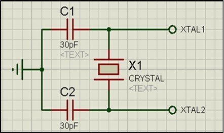
Reset Circuit
In order to prevent unexpected situation or sudden failure in the process of single-chip microcomputer debugging, the reset function of single-chip microcomputer is designed in the design of single-chip microcomputer, and the reset function of single-chip microcomputer (sometimes called setting function). Can directly restore the system from the existing state to an initialization state.
The principle of the reset circuit is: when the RST reset pin of the single-chip microcomputer receives more than one 2us level signal, the reset function of the single-chip microcomputer can be realized as long as the charge and discharge time of the capacitor in the reset circuit is longer than 2us.
The reset mode can be divided into two types: key reset and power-on reset.
Figure 5 shows the reset circuit of 51 single-chip microcomputer
Figure 5.Single chip microcomputer reset circuit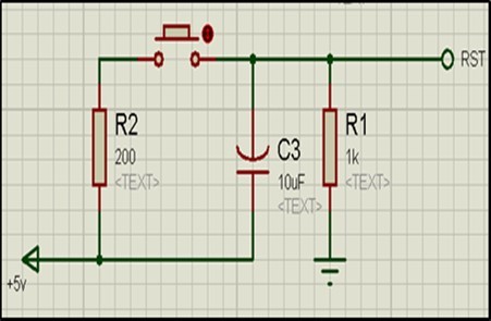
Hall Sensor
A sensor is a device or device that can feel the specified measurement and can be converted into available output signals according to a certain rule, which is usually composed of sensitive elements and conversion elements.
Because the output signal of rotary speed sensor is pulse signal, high stability, strong anti-interference ability, simple structure, low cost, high performance reliability and so on, rotary speed measurement is widely used in vehicle speed measurement.
The rotary speed measurement sensor is now roughly divided into two types, one is the contact speed sensor, the other is the non-contact speed sensor.
The speed sensor used in this design is a Hall sensor made of Hall effect.
Applying a magnetic field perpendicular to the current direction on the semiconductor can offset the carrier trajectory inside the semiconductor and accumulate on both sides of the semiconductor material to form an electric field perpendicular to the current direction. a stable potential difference, that is, Hall voltage, will be formed on both sides after the balance of Lorentz force and electric field repulsion. This effect is called Hall effect.
Under the action of the external magnetic field, when the magnetic induction intensity exceeds the conduction threshold BOP, the Hall circuit output tube turns on and the output level is low.
After that, when B increases, it still maintains the conduction state.
If the B value of the external magnetic field is reduced to BRP, the output tube is cut off and the output level is high.
We call BOP a work point, BRP a release point, and BOP-BRP=BH a backlash.
The existence of backlash enhances the anti-interference ability of the switching circuit.
During the measurement, the integrated Hall switch is fixed, the magnet is moved, and the direction of movement is in the direction of the axis of the magnet and the Hall switch.
The experiment shows that when the magnet and the Hall switch move closer to a certain position, the Hall switch is turned on.
After the two move a certain distance, the Hall switch is disconnected.
Display Module
Liquid Crystal Display is Abbreviated to LCD.
Liquid crystal display is made of liquid crystal. Liquid crystal is a kind of object with characteristics between liquid and solid. Liquid crystal not only has the optical properties of solid crystal, but also has the flow characteristics of liquid. We use the photoelectric effect of liquid crystal to make liquid crystal display.
LCD1602, also known as 1602 character LCD, is a liquid crystal module that can display dot matrix characters such as numbers, letters, symbols and so on. LCD1602 consists of 16 × 2 5 × 7 or 5 × 11 dot matrix character bits, each of which can display one character.
In order to realize the timing function of bicycle clock, this design uses DS1302 clock chip, which can time year, month, week, day, hour, minute, second and so on.
Design and Introduction of System Software
System Software Design
The programming of the software part of the system is programmed in C language and adopts the idea of modularization. Each module has a corresponding calling function, which can be called directly when it is used in the main function.
Display Module Design
The display module subroutine uses LCD dynamic scanning. Is the first MCU P2.2 port and LCD port E connected. Then connect the P2.0 port of SCM with RS (data/command selection terminal) of LCD, P0.0~P0.7 port of SCM with D0~D7 data port of LVD, and then send the value of the number to be displayed to P0 port. Then call the delay program displayed on the LCD screen.
Velocity Processing Flow Chart
The speed processing module can calculate the instantaneous speed of the bicycle, and then judge whether it exceeds the preset speed value. If it overspeeds, it will alarm and display the speed.
The Simulation
The simulation software used in this design is Proteus and Proteus. The simulation results are shown in Figure 6.
Figure 6.Simulation result
Conclusion
After many times of debugging, the system now has good stability, and can realize the functions of bicycle speed measurement and display, display time, overspeed alarm, reminder and lighting.
Of course, there are still many shortcomings in this system, such as the large size of the hardware system, low integration, not suitable to carry and install on the bike, and there are still many places on the software that need to be optimized.
References
- 1.FAN Hua. (2021) A CMOS Hall sensor modeling with readout circuitry and microcontroller processing for magnetic detection. Review of Scientific Instruments. 92(3), 034707.
- 2.ZHANG Chunlei. (2021) Analog-Hall-Sensor-Based Position Detection Method With Temperature Compensation for Permanent-Magnet Linear Motor. , IEEE Transactions on Instrumentation 70, 1-11.
- 3.Lee Kai Jun. (2018) Display technology comparison and new progress. LCD and display. 33(1), 74-84.
- 4.KASHEVNIK Alexey. (2018) Context-based cyclist intelligent support: An approach to e-bike control based on smartphone sensors. In: Internet of Things, Smart Spaces, and Next Generation Networks and Systems. , Cham 16-22.
- 6.YAJING Yu. (2020) Application analysis of single chip microcomputer technology in IOT electronic intelligent products. Microprocessors and Microsystems. 103468.